


Scales are gravimetric devices. In other words, they are devices that measure the force that gravity exerts on mass. Scales can be classified as two types: differential and integral weighing devices.
Differential Weighing Devices
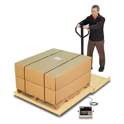
Differential weighing devices are the most common. You begin at one weight on a scale and then add or subtract weight to give you the difference between the beginning and ending reading. For example, a truck scale starts at one reading, generally zero, and then goes to a different weight reading when you drive a truck onto the scale platform. The difference between the two readings is the weight of the truck. Truck scales, rail scales, platform scales, shipping scales, retail POS scales, counting scales, etc. all operate on this principle.
Batching scales weigh ingredients into a weigh hopper on a differential basis, one ingredient at a time. Bulk weighers weigh and dump into and out of a bulk material weigh hopper to record the high weight, the low weight, and the difference, which is the total weight transferred of bulk materials. Loss-in-weight feeders use a feeding device to empty a weigh hopper at a controlled rate using the rate of change of weight (the differential weight change) as the measuring element.
Integrating Weighing Devices
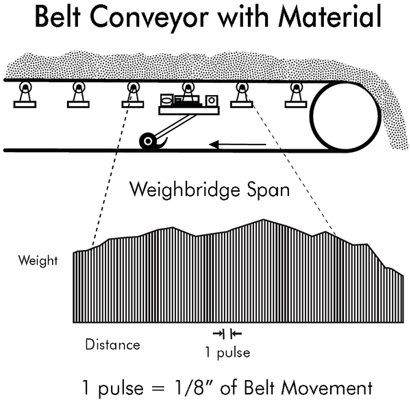
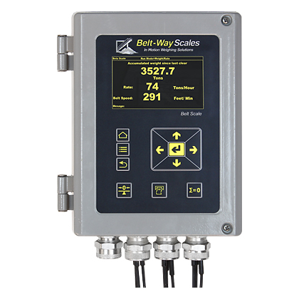
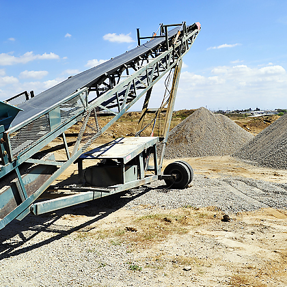
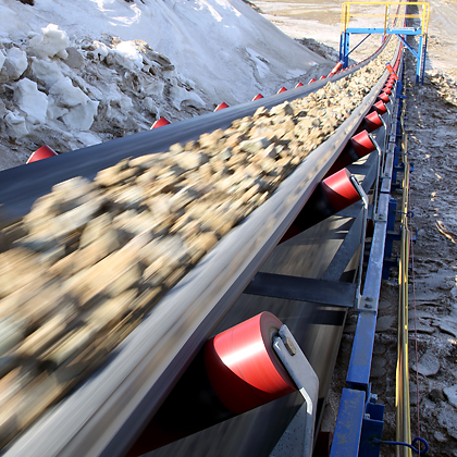
Integrating weighing devices are the second category of scales. Conveyor belt scales are integrating weighing devices that use a simple integral calculus summation process to measure a conveyed quantity of material. Two variables are involved: weight and speed. A weight function measures the weight of a small section of a conveyor. The gross weight on the scale is the weight of the belt, the belt conveyor idler, and the material on the belt. The net weight of material only is the gross weight less the weight of the supported section of the belt and the scale idler. The speed function is the second variable to be measured. Most modern speed sensors are rotary digital pulse generators. These can be optical, magnetic or other on/off sensing units. They are mounted on a pulley or wheel that rotates as the belt moves. They generate an on/off signal as they move which is directly proportional to the distance the belt moves and the speed of the belt.
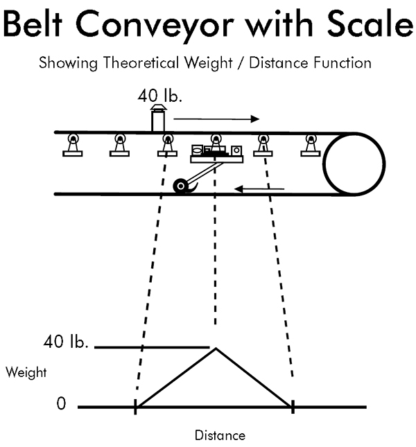
In order to better understand this belt movement combined with the weighing function, let us look at a single weight travelling along a conveyor as it crosses over a weighing idler section. A triangular shaped weight function is generated as it goes from zero to the full weight and back to zero. Every particle of material that goes over the scale generates its own triangular function. The total weight sensed at any particular position of the conveyor is the sum of all particles in the weighing area with respect to their individual triangular waveforms and their position in the scale weighing area. This weight function is a representation of the weight per unit distance at any one point on the conveyor belt. This is usually represented in lbs/ft or kg/m.
Formulas Used for Commonly Displayed Data:
Total weight = Weight / unit distance x distance
Rate = Change of total weight
————————————
Time
Belt speed = Distance
————————
Time
As the conveyor moves a small discrete distance measured by the speed sensor, a portion of the weight is totaled. If the belt loading is 50 lb/ft and the belt moves 1/100 of a foot, then the totalizer will add 0.5 pound to the total. This happens at a relatively high speed. A conveyor travelling 300 ft/minute will generate 30,000 additions per minute or 500 readings per second. We use multiple readings per pulse to gain higher resolution. This equates to 4,000 analog weight readings per second in the above example.
Using integral calculus, there are several ways to add up the weight between pulses. These are left-hand approximation, right-hand approximation, trapezoidal approximation, and Simpson’s rule approximation. The left- and right-hand approximations sum rectangular areas that intersect the curve at leading or trailing sides of the curve’s intersection between two pulses. The trapezoidal approximation give the area of a trapezoid that goes between the leading and trailing curve intersection points to form a trapezoidal shape. Simpson’s Rule takes two-pulse width spaces and uses the beginning, middle, and end points to fit a parabolic curve to approximate the area under the two-pulse width area. This is the most accurate mathematical model, but it involves more extensive computational algorithms.
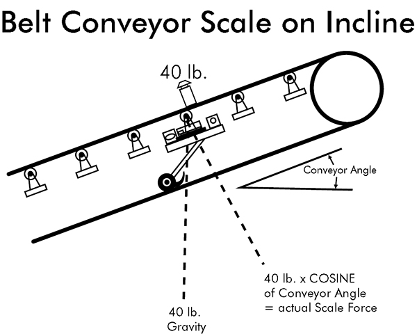
Another factor that effects the weight-sensing element on a conveyor belt scale is the angle of the conveyor from a level position. The force seen by the scale is proportional to the actual weight times the cosine of the conveyor angle. A level conveyor has an angle of zero degrees (Cos. (0)=1). Therefore, the force of gravity and the resultant force on the scale would be the same. A 40-pound weight would have a measured force equal to 40 pounds. A conveyor at 30 degrees has a cosine = 0.866. Therefore, a weight of 40 pounds on the conveyor would result in a measured force of 34.64 lbs on the scale.
A fixed angle conveyor scale can be compensated by a change of gain in the scale. In the above example, 34.64 lbs/cos. (30)=40 pounds. This can be a fixed number if the conveyor angle is fixed. However, some stacker conveyors change angle of elevation as they operate. An angle compensator can measure the angle of the conveyor and compensate the scale reading to correct for changing angle.
Types of Belt Scale Weighing Technologies
Many different types of weighing technologies have been used over the years for conveyor belt scales.
The first belt scales used mechanical integrators. The speed of the belt drives a disk. A ball or another disk rolls on this disk at right angles to the speed disk. The position of the ball or second disk is controlled by the weight on the scale. If the ball is in the center of the speed disk, it does not rotate at all. As the ball is moved to the outside, it rotates faster and faster. The speed of the ball is a mechanical multiple of the speed of disk and the position of the ball on the disk. The ball is connected to a shaft that drives a totalizer. The speed of this shaft is the rate.
Another method of determining the load on a conveyor belt was to use a nuclear source on one side of the belt and a detector on the other side. The more material that is on the belt, the less radiation is detected. You get an inversely proportional signal of absorbing mass on the belt. Using this along with belt speed, you could make a belt scale. These were never very wide spread in actual use.
LVDT’s (linear variable differential transformers) are position sensing devices that have been used in conjunction with spring mechanisms to measure belt weight. They are non-contacting sensors and generally have spring mechanisms that are rugged in nature which gives them very good overload characteristics. On the down side, they can exhibit problems with thermal effects on the mechanical springs. These effects can be both on zero because of thermal expansion and on the span due to modulus of elasticity changes.
Strain gauge load cells are commonly used in scales today. Many have been adapted to mechanical lever scales using a lever system to sum forces at a single point where a load cell is used to read the resultant force electronically at this point. These scales were common for retrofit installations on truck scales, for example. Also, strain gauge load cells were initially very expensive and limited to in-line tension and compression forces. This made mechanical hybrid load cell mechanisms popular. Some belt scales are made with this technology today, but their use is declining.
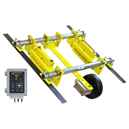
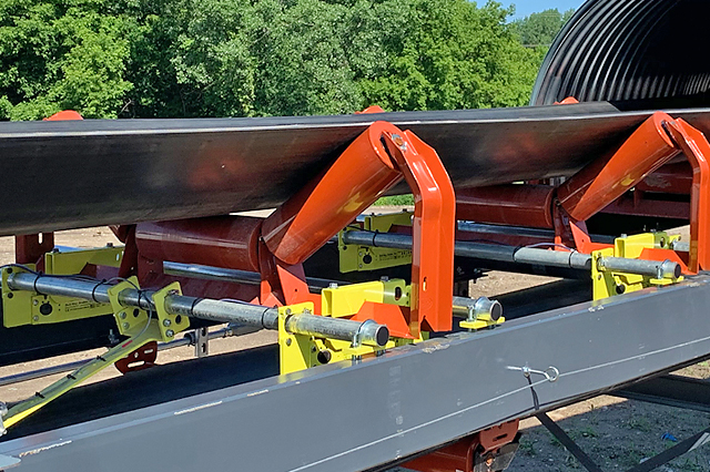
Today, most scales are full strain gauge suspension types. They use little or no mechanical mechanisms and the load platform is directly supported by the load cell system. Most new conveyor belt scales use this technology. Overload stops are built into the load cell mounting systems to make them rugged and reliable. Also, they are simple in their overall design. Single point suspension load cell designs allow for off-center loading. This also compensates for any extraneous side loading that could affect the true weight component of the belt load forces that we are measuring.
There are advantages and disadvantages when considering conveyor belt scales. As an integrating device, a conveyor belt scale is a very compact device that fits into any conveying system. The scale handles large quantities of raw materials on a continuous basis. It does not require large batch hoppers, truck scales, or rail scales. It can handle rates that make the application of differential scales almost impractical. Loading and unloading ships is one example.
Belt scales have their weak points. First, belt scales can run for extended periods of time without returning to zero. This means that any buildup on the scale that affects the zero will not be detected until the scale is run empty. A zero error is not a one-time error. This error is continuously added along with the weight or actual material. Also, extraneous forces such as wind loading, changing belt tension, excessive vibration, and mechanical interference with the scale can cause errors in the weighing system. The scale does not know the difference between the forces from actual material we are trying to weigh and the forces from external noise. Although this is true of all scales, the ratio of signal to noise is much better on differential weighing devices than on integrating devices. Integrating belt scales are weighing a small portion of weight on a continual basis and external noise can be significant. Care must be taken to correctly install a belt scale and to protect it from external influences.